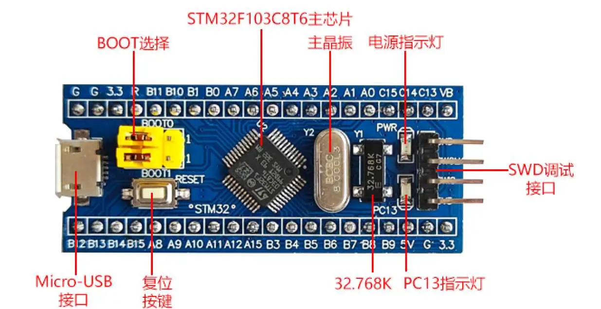
C8T6串口概述
STM32F103C8T6微控制器包含3个串口模块:
-
USART1 (高级串口)
-
USART2
-
USART3 (部分型号可能标记为UART3)
-
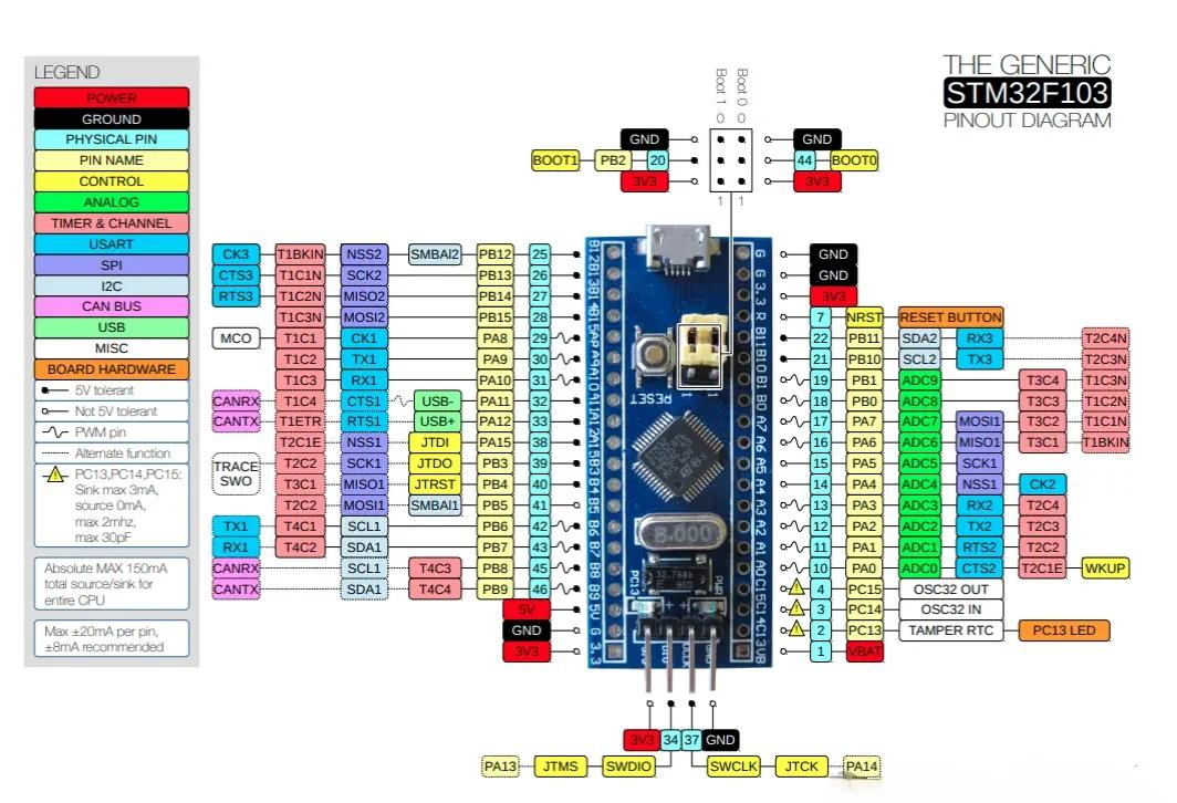
引脚分布图
-
USART1 (串口1)
基本特性
-
类型:全功能USART(通用同步异步收发器)
-
通信模式:
-
全双工异步通信
-
单线半双工通信
-
同步通信(需要外部时钟)
-
支持LIN总线协议
-
支持IrDA SIR ENDEC规范
-
支持智能卡协议(ISO7816)
-
引脚分配
-
TX:PA9 (主用), PB6 (重映射)
-
RX:PA10 (主用), PB7 (重映射)
-
CK:PA8 (同步模式时钟, 主用), PB6 (重映射)
-
CTS:PA11 (主用), PB13 (重映射)
-
RTS:PA12 (主用), PB14 (重映射)
性能参数
-
最高支持4.5Mbps传输速率(在72MHz系统时钟下)
-
可编程数据字长度(8或9位)
-
可配置的停止位(1或2位)
-
可选的奇偶校验位(偶校验/奇校验)
USART2 (串口2)
基本特性
-
类型:基本USART
-
通信模式:
-
全双工异步通信
-
单线半双工通信
-
不支持同步模式和硬件流控制
-
引脚分配
-
TX:PA2 (主用), PD5 (重映射)
-
RX:PA3 (主用), PD6 (重映射)
性能参数
-
最高支持2.25Mbps传输速率
-
可编程数据字长度(8或9位)
-
可配置的停止位(1位)
-
可选的奇偶校验位(偶校验/奇校验)
USART3 (串口3)
基本特性
-
类型:基本UART(在STM32F103C8T6上功能较USART1简化)
-
通信模式:
-
全双工异步通信
-
单线半双工通信
-
不支持同步模式
-
引脚分配
-
TX:PB10 (主用), PC10 (部分重映射), PD8 (完全重映射)
-
RX:PB11 (主用), PC11 (部分重映射), PD9 (完全重映射)
性能参数
-
最高支持2.25Mbps传输速率
-
可编程数据字长度(8位)
-
可配置的停止位(1位)
-
可选的奇偶校验位(偶校验/奇校验)
主要区别对比
| 特性 | USART1 | USART2 | USART3 |
|---|---|---|---|
| 类型 | 全功能USART | 基本USART | 基本UART |
| 同步模式 | 支持 | 不支持 | 不支持 |
| 硬件流控制 | 支持(CTS/RTS) | 不支持 | 不支持 |
| 最高速率 | 4.5Mbps | 2.25Mbps | 2.25Mbps |
| DMA支持 | 发送和接收 | 发送和接收 | 发送和接收 |
| 中断源 | 丰富 | 基本 | 基本 |
| 时钟源 | PCLK2(APB2) | PCLK1(APB1) | PCLK1(APB1) |
时钟配置
-
USART1挂载在APB2总线上(最高72MHz)
-
USART2和USART3挂载在APB1总线上(最高36MHz)
应用建议
-
USART1:推荐用于高速通信或需要硬件流控制的场景
-
USART2/USART3:适合普通速率通信,节省硬件资源
-
多串口应用时,可根据外设连接方便性选择不同的串口
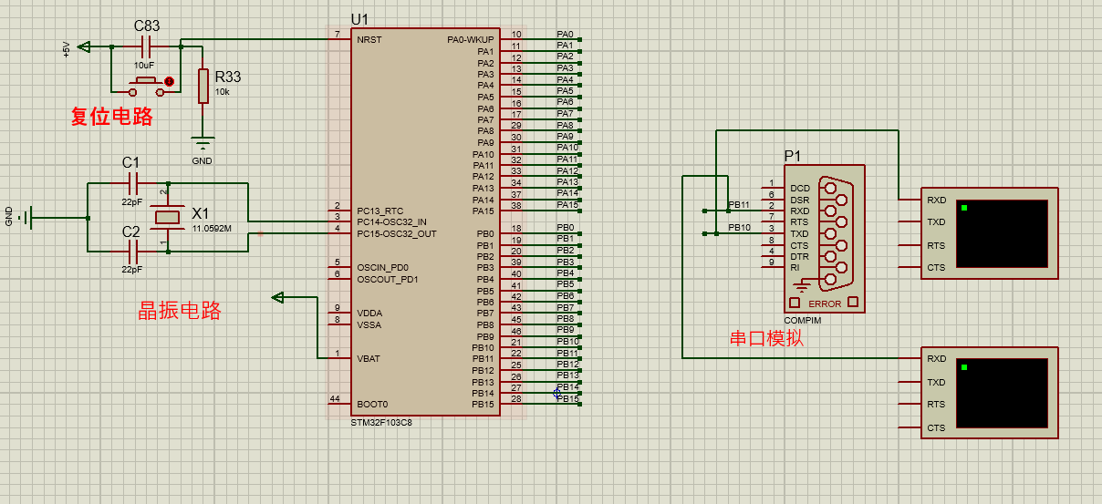
STM32 代码实现
注意:本次采用串口1 tx :pa9 rx:pa10实现。
proteus 仿真电路图
虚拟串口配置:虚拟串口配置教程
串口3实现代码
usart.c
#include "usart3.h"
#include "stm32f10x.h"
#include "sys.h"static int Send_buf[10] = {0} ; u8 USART3_RX_STA = 0; //接收状态标记
u8 USART3_RX_CMD;void USART3_Init(u32 bound)
{//GPIO端口设置GPIO_InitTypeDef GPIO_InitStructure;USART_InitTypeDef USART_InitStructure;NVIC_InitTypeDef NVIC_InitStructure;RCC_APB1PeriphClockCmd(RCC_APB1Periph_USART3, ENABLE); //使能USART3时钟RCC_APB2PeriphClockCmd(RCC_APB2Periph_GPIOB | RCC_APB2Periph_AFIO, ENABLE); //使能GPIOB时钟,端口复用时钟//USART3_TX GPIOB.10GPIO_InitStructure.GPIO_Pin = GPIO_Pin_10; //PB10GPIO_InitStructure.GPIO_Speed = GPIO_Speed_50MHz; //万勿省略此条,一经删除则发送不了数据GPIO_InitStructure.GPIO_Mode = GPIO_Mode_AF_PP; //复用推挽输出GPIO_Init(GPIOB, &GPIO_InitStructure); //初始化GPIOB.10//USART3_RX GPIOB.11GPIO_InitStructure.GPIO_Pin = GPIO_Pin_3; //PB11GPIO_InitStructure.GPIO_Mode = GPIO_Mode_IN_FLOATING; //浮空输入GPIO_Init(GPIOA, &GPIO_InitStructure); //初始化GPIOB.11 //USART 初始化设置USART_InitStructure.USART_BaudRate = bound; //串口波特率USART_InitStructure.USART_WordLength = USART_WordLength_8b; //字长为8位数据格式USART_InitStructure.USART_StopBits = USART_StopBits_1; //一个停止位USART_InitStructure.USART_Parity = USART_Parity_No; //无奇偶校验位USART_InitStructure.USART_HardwareFlowControl = USART_HardwareFlowControl_None; //无硬件数据流控制USART_InitStructure.USART_Mode = USART_Mode_Rx | USART_Mode_Tx; //收发模式USART_Init(USART3, &USART_InitStructure); //初始化串口3 USART_ITConfig(USART3, USART_IT_RXNE, ENABLE); //开启串口接受中断//Usart3 NVIC 配置NVIC_InitStructure.NVIC_IRQChannel = USART3_IRQn;NVIC_InitStructure.NVIC_IRQChannelPreemptionPriority=3 ; //抢占优先级3NVIC_InitStructure.NVIC_IRQChannelSubPriority = 3; //子优先级3NVIC_InitStructure.NVIC_IRQChannelCmd = ENABLE; //IRQ通道使能NVIC_Init(&NVIC_InitStructure); //根据指定的参数初始化VIC寄存器USART_Cmd(USART3, ENABLE);}void USART3_SendByte(uint8_t Data) //串口发送一个字节;字节 (byte) 1byte=8bit
{while(USART_GetFlagStatus(USART3, USART_FLAG_TXE) == RESET); //USART_FLAG_TXE发送寄存器空USART_SendData(USART3, Data); //从串口2发送传入的数据while(USART_GetFlagStatus(USART3, USART_FLAG_TC) == RESET); //USART_FLAG_TC发送完成标志
}void USART3_IRQHandler(void) //串口2中断服务程序
{u8 Res=0;if(USART_GetITStatus(USART3, USART_IT_RXNE) != RESET) //接收中断{Res=USART_ReceiveData(USART3); //读取接收到的数据USART3_RX_CMD = Res; //把接收到的数据传递给USART_RX_CMDUSART3_RX_STA=1;USART3_SendByte(Res); //去进入主函数WHILE语句 }
}void USART3_SendCmd(int len)
{ int i = 0 ;USART3_SendByte(0x7E); //起始for(i=0; i<len; i++)//数据{ USART3_SendByte(Send_buf[i]); //len 为8 ;依次将Send_buf[0]、Send_buf[1] !!!Send_buf[8] 发送出来 }USART3_SendByte(0xEF); //结束}void Uart3_SendCMD(int CMD ,int dat1 , int dat2 ,int dat3)
{Send_buf[0] = 0xff; //保留字节 Send_buf[1] = 0x06; //长度Send_buf[2] = CMD; //控制指令Send_buf[3] = (int)(dat1); //Send_buf[4] = (int)(dat2); //datah2Send_buf[5] = (int)(dat3); //datal3USART3_SendCmd(6); //发送此帧数据
}void USART3_SendString(char *str)
{while (*str){while (USART_GetFlagStatus(USART3, USART_FLAG_TC) == RESET);USART_SendData(USART3, *str++);}
}
usart.c
#ifndef __USART3_H
#define	__USART3_H#include "stm32f10x.h"
#include <stdio.h>
#include "sys.h" #define EN_USART3_RX 			1		//使能(1)/禁止(0)串口1接收extern u8 USART3_RX_STA;         		//接收状态标记
extern u8 USART3_RX_CMD;         	//void Init_hardware_usart2_(u32 bound);
void USART3_Init(u32 bound);void USART3_IRQHandler(void);void USART3_SendByte(uint8_t  Data); void Uart3_SendCMD(int CMD ,int dat1 , int dat2 ,int dat3);
void USART3_SendString(char *str);#endif
主函数
#include "stm32f10x.h"
#include "delay.h"
#include "oled.h"#include "usart3.h"//蜂鸣器初始化---------------------------------------------------------------------------------------
#define BEEP_GPIO_PIN_PROT GPIOB
#define BEEP_GPIO_PIN GPIO_Pin_5
void Beep_Init()
{GPIO_InitTypeDef GPIO_InitStructure;RCC_APB2PeriphClockCmd(RCC_APB2Periph_GPIOB,ENABLE);GPIO_InitStructure.GPIO_Pin =BEEP_GPIO_PIN ;GPIO_InitStructure.GPIO_Mode = GPIO_Mode_Out_PP;GPIO_InitStructure.GPIO_Speed = GPIO_Speed_50MHz;GPIO_Init(BEEP_GPIO_PIN_PROT, &GPIO_InitStructure);//GPIO_ResetBits(BEEP_GPIO_PIN_PROT,BEEP_GPIO_PIN);//默认给0,关闭GPIO_ResetBits(BEEP_GPIO_PIN_PROT,BEEP_GPIO_PIN);
}
//蜂鸣器驱动
void Beep_Run(unsigned char x)
{if(x==1){GPIO_SetBits(BEEP_GPIO_PIN_PROT,BEEP_GPIO_PIN);}else{GPIO_ResetBits(BEEP_GPIO_PIN_PROT,BEEP_GPIO_PIN);}}int main()
{SystemInit();//配置系统时钟为72M	delay_init(72);//延时初始化OLED_Init();//OLED 屏幕USART3_Init(9600);USART3_SendString("hello");while (1){}//while line}
测试效果


)


)


:最大子段和(分治思想))

)